


Vòng bi chống quay ngược (Blackstop cam clutch)


Thông tin sản phẩm
GIỚI THIỆU
Đặc trưng
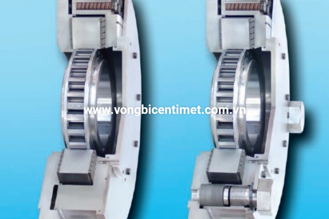
Freewheels tích hợp FXRV và FXRT là những loại freewheels không có gối đỡ và có bộ phận nâng rời X. Chúng bao gồm các Freewheels FXM tích hợp (tham khảo từ trang 64 đến 69) với bộ giới hạn mô-men xoắn bổ sung.
Thanh nâng rời X đảm bảo bánh xe hoạt động không bị mài mòn khi vòng trong quay ở tốc độ cao.
Các trang sức tự do FXRV và FXRT được sử dụng như:
➧Bản lùi
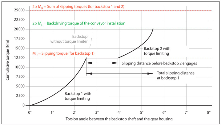
để lắp đặt băng tải liên tục với nhiều ổ, trong đó mỗi ổ được trang bị backstop riêng. Trong việc lắp đặt băng tải liên tục với nhiều ổ đĩa như vậy, điều quan trọng là phải xem xét vấn đề về sự phân bổ không đồng đều của mô-men xoắn ngược cho các ổ đĩa và điểm dừng riêng lẻ. Ngay sau khi quá trình cài đặt dừng lại, toàn bộ mô-men xoắn lùi được áp dụng chủ yếu cho một điểm lùi duy nhất, do sự khác biệt trong hoạt động và độ đàn hồi của các ổ đĩa liên quan. Trong các cơ sở lắp đặt có trang bị lùi không có bộ hạn chế mô-men xoắn, các hộp số riêng và các điểm dừng tương ứng phải được thiết kế để chứa toàn bộ mô-men xoắn của việc lắp đặt băng tải để đảm bảo an toàn.
Vấn đề về sự phân bố không đều của mô-men xoắn lùi được giải quyết bằng cách sử dụng điểm lùi FXRV và FXRT với giới hạn mô-men xoắn. Bộ giới hạn mô-men xoắn được tích hợp trong mặt sau trượt tạm thời khi vượt quá mô-men xoắn quy định cho đến khi các điểm dừng khác liên tiếp xảy ra. Bằng cách này, toàn bộ mômen quay ngược của việc lắp đặt băng tải được phân phối đến các hộp số và điểm dừng riêng lẻ. Hơn nữa, mô-men xoắn cực đại động xảy ra trong quá trình khóa được giảm xuống, do đó bảo vệ hộp số chống lại mô-men xoắn cực đại làm hỏng. Vì lý do này, việc sử dụng mặt sau FXRV và FXRT với giới hạn mô-men xoắn trong việc lắp đặt băng tải liên tục với nhiều ổ đĩa cho phép ứng dụng các hộp số có kích thước nhỏ hơn.
Thuận lợi
• Bảo vệ hộp số khỏi quá tải bằng cách phân bổ tải không đều trong nhiều ổ
• Bảo vệ hộp số khỏi mô-men xoắn cực đại động trong quá trình khóa
• Có thể sử dụng các hộp số nhỏ hơn mà không ảnh hưởng đến sự an toàn
• Bảo vệ các điểm dừng lại, vì mô-men xoắn đỉnh động được giảm bằng cách trượt tạm thời
|
Integrated Freewheels FXRV with |
Integrated Freewheels FXRT with |
|
Selection torque |
P L = Lifting capacity per drive at full load [kW] = Lifting height [m] multiplied by the load that is being conveyed per second divided by the number of drives [kN/s] P 0 = Nominal power of motor [kW] n SP = Speed of backstop shaft [min -1 ] h = Efficiency of installation Lifting capacity = Lifting capacity + Power loss After calculating M A , the size of the particular backstop must be selected in accordance with the catalogue tables in such a way that in all cases this applies: M R ^ M A M R = Maximum slipping torque of the particular backstop in accordance with the table values on pages 74 and 75 [Nm] |
Approximate values for h:
|

|
Example |
|

|
Freewheel Size |
Type |
Slipping torque |
Sprag lift-off at inner ring speed min-1 |
Max. speed |
mm |
mm |
Bore d |
mm |
mm |
max. mm |
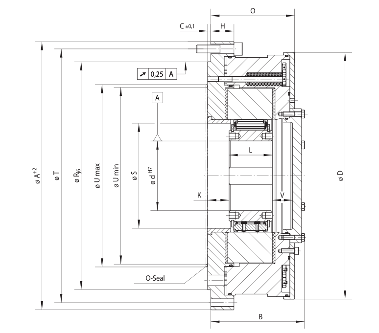
A |
B |
C |
D |
G** |
H |
K |
L |
O |
R |
S |
T |
min. mm |
U*** |
V |
Z** |
w |
|
|
FXRV 85 - 40 |
MX |
1 400 |
430 |
6 000 |
45 |
50 |
60 |
65 |
|
|
65 |
330 |
143 |
6 |
295 |
M 12 |
37 |
29 |
60 |
127 |
280 |
110 |
308 |
165 |
215 |
43 |
6 |
57 |
|
FXRV 100 - 50 |
MX |
2 300 |
400 |
4 500 |
45 |
50 |
55 |
60 |
70 |
75 |
80* |
350 |
150 |
6 |
311 |
M 12 |
39 |
31 |
70 |
134 |
300 |
125 |
328 |
180 |
240 |
38 |
6 |
65 |
|
FXRV 120 - 50 |
MX |
3 400 |
320 |
4 000 |
60 |
65 |
70 |
75 |
80 |
95 |
95 |
400 |
150 |
6 |
360 |
M 16 |
36 |
31 |
70 |
134 |
340 |
145 |
373 |
200 |
260 |
38 |
6 |
86 |
|
FXRV 140 - 50 |
MX |
4 500 |
320 |
3 000 |
65 |
90 |
100 |
110 |
|
|
110 |
430 |
160 |
6 |
386 |
M 16 |
36 |
31 |
70 |
134 |
375 |
165 |
403 |
220 |
280 |
50 |
6 |
102 |
|
FXRV 170 - 63 |
MX |
9 000 |
250 |
2 700 |
70 |
85 |
90 |
100 |
120 |
|
130 |
500 |
175 |
6 |
460 |
M 16 |
43 |
40 |
80 |
156 |
425 |
196 |
473 |
250 |
340 |
38 |
6 |
163 |
|
FXRV 200 - 63 |
MX |
12 500 |
240 |
2 100 |
130 |
|
|
|
|
|
155 |
555 |
175 |
6 |
516 |
M 16 |
49 |
40 |
80 |
156 |
495 |
226 |
528 |
275 |
390 |
38 |
6 |
205 |
|
FXRV 240 - 63 |
LX |
21 200 |
220 |
3 000 |
|
|
|
|
|
|
185 |
710 |
195 |
8 |
630 |
M 20 |
50 |
50 |
90 |
170 |
630 |
290 |
670 |
355 |
455 |
45 |
12 |
347 |
|
FXRV 260 - 63 |
LX |
30 000 |
210 |
2 500 |
|
|
|
|
|
|
205 |
750 |
205 |
8 |
670 |
M 20 |
50 |
50 |
105 |
183 |
670 |
310 |
710 |
375 |
500 |
40 |
12 |
411 |
|
FXRV 290 - 70 |
LX |
42 500 |
200 |
2 500 |
|
|
|
|
|
|
230 |
850 |
218 |
8 |
755 |
M 24 |
52 |
50 |
105 |
190 |
730 |
335 |
800 |
405 |
560 |
48 |
12 |
562 |
|
FXRV 310 - 96 |
LX |
53 000 |
195 |
2 100 |
|
|
|
|
|
|
240 |
900 |
260 |
10 |
800 |
M 24 |
63 |
63 |
120 |
240 |
775 |
355 |
850 |
435 |
600 |
69 |
12 |
792 |
|
FXRV 360 - 100 |
LX |
75 000 |
180 |
1 800 |
|
|
|
|
|
|
280 |
975 |
267 |
10 |
870 |
M 30 |
63 |
63 |
125 |
243 |
850 |
400 |
925 |
485 |
670 |
71 |
12 |
942 |
|
FXRV 410 - 100 |
LX |
100 000 |
170 |
1 500 |
|
|
|
|
|
|
300 |
1 060 |
267 |
10 |
950 |
M 30 |
63 |
63 |
125 |
243 |
950 |
450 |
1 000 |
535 |
750 |
71 |
12 |
1053 |
Keyway according to DIN 6885, page 1 • Tolerance of keyway width JS10. * Keyway according to DIN 6885, page 3 • Tolerance of keyway width JS10.
** Z = Number of fastening holes for screws G (DIN EN ISO 4762) on pitch circle T. *** Area for O-ring sealing.
See page 73 for determination of selection torque. Other freewheel sizes upon request.
|
Torques |
Mounting |
Example for ordering |
Sản phẩm liên quan


- Vòng bi WANDA
- Vòng bi chống quay ngược (Blackstop cam clutch)
- Vòng bi mắt trâu (Spherical ball bearing with seat)
- Vòng bi kim (Needle bearing)
- Vòng bi một chiều (Clutch bearing)
- Hub bearing
- Vòng bi côn (Tapered roller bearing)
- Vòng bi trượt (Linear slider)
- Vòng bi chà (Thrust bearing)
- Vòng bi tròn (ball bearing)
- Vòng bi gối đỡ (pillow Block Unit)
- Gối đỡ chống quay ngược (One Way Cam Clutch)
- Vòng bi lệch tâm
- Măng Xông
HỖ TRỢ TƯ VẤN

Hot line:0912050286
0907030784
CSKH: 0908088564
Email: thietbicentimet@gmail.com.vn

